In a previous “Tip of the Month” we briefly discussed the need for understanding a phase diagram in a gas processing system. In this Tip we will try to clearly define the areas of a light mixture phase envelope and the terms necessary to “talk intelligently” about the shape of a mixture phase diagram. This will allow us to look at the methods of calculation and their limitations in another tip and eventually define our areas of risk in the operation or design of a facility based on the phase diagram.
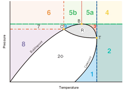
The figure is a “generic” phase diagram. The general areas are 1) to the left of the phase diagram – liquid; 2) to the right of the phase diagram – vapor; 3) inside the phase diagram – two phase; and 4) above the phase diagram – dense phase.

However, note that there are several sub-areas that might be questioned as to their exact phase name. For instance the area marked “3” is “above the phase diagram but below the highest pressure that two phases can exist. Should this region be called “vapor” or “dense phase?” Or perhaps the more important question is: “Do I care?” The answer to the second question is “yes, sometimes.” The answer to the first question is “maybe, sometimes.” With these two very clear answers in mind, maybe the general criteria needs to be further defined.
For a quick review let’s start with pure component and mixture phase diagram differences.
For a pure component an acceptable definition of the CRITICAL POINT is “the highest temperature and pressure that two phases can exist for a given component.” The critical point for our generic mixture is point C. This is an experimentally determinable point and is the point where the mixture properties in the vapor phase and the liquid phase are the same. As shown on the diagram there is a considerable region at temperatures higher than the critical point that is two phase and a smaller region of pressures higher than the critical pressure that is also two phase.
Two new terms are introduced to describe these regions and their limits. The first term is the name given to the highest temperature at which two phases can coexist. This is point T in the figure. This point is called the cricondentherm. The second term is the highest pressure at which two phases can coexist – point B. This point is called the cricondenbar. Any facility that operates at a temperature always higher than the cricondentherm will never condense liquids. Any process that is operated at a pressure higher than the cricondenbar will not be two-phase. A process in this region can be liquid, vapor or “dense phase”, but never two at the same time. Dense phase pipelines are designed to always be at pressures above the cricondenbar. Dewpoint control is often a matter of controlling the temperature of the cricondentherm for sales gas so that the gas pipeline is not two-phase at the coldest temperature in the system.
Now back to defining each of the areas in the figure. The easy areas first: Areas 1 and 2 are generally called vapor. Areas 7 and 8 are generally called liquid. Areas 5a and 5b are generally called dense phase.
Area 3 (vapor or dense phase) is generally called a vapor because it is below the cricondenbar (B) and condenses liquid when the pressure is decreased at constant temperature.
Area 4 (vapor or dense phase) could be called vapor or dense phase depending on the exact definition used. For instance, if all areas above the cricondenbar (B) are defined as dense phase then area 4 is dense phase. If all areas to the right of the cricondentherm (T) are defined as vapor then area 4 is vapor.
Area 6 (liquid or dense phase) could be called liquid or dense phase again depending on our exact definition. If all areas above the cricondenbar (B) are defined as dense phase then it is dense phase. If all areas to the left of the critical point (C) are defined as liquid then it is liquid.
Area 9 (liquid, vapor, or dense phase) could be interpreted as any of the phases depending on your definitions. Some people would define any area to the left of the cricondenbar (B) as a liquid. This would imply that areas 5b, 6 and 9 are liquid. Most people would define any single-phase fluid outside of the dewpoint line and below the cricondenbar (B) as a vapor. This would imply that area 9 is a vapor. Some people would define any single-phase fluid above the critical point (C) as dense phase.
My personal preferences are:
Area 1 – Vapor
Area 2 – Vapor
Area 3 – Vapor
Area 4 – Vapor
Area 5 – Dense phase
Area 6 – Liquid
Area 7 – Liquid
Area 8 – Liquid
Area 9 – Vapor
These choices are made based on the answer to the “Do I care?” question. In a future tip we will discuss how these names (doesn’t a rose by any other name smell just as sweet?) do make a difference from a simulation point of view and from an interpretation of real world problems.
In the meantime Chapter 4 of Volume I Gas Conditioning and Processing discusses these topics in more detail.
By: Dr. Larry L. Lilly
