When a pure compound, in gaseous or liquid state, is heated and compressed above the critical temperature and pressure, it becomes a dense, highly compressed fluid that demonstrates properties of both liquid and gas. For a pure compound above critical pressure and critical temperature, the system is oftentimes referred to as a “dense fluid” or “super critical fluid” to distinguish it from normal vapor and liquid (see Figure 1 in December 2009 Tip Of The Mont (TOTM) [1] for carbon dioxide and in January 2010 TOTM [2] for a typical natural gas). Dense phase is a fourth (Solid, Liquid, Gas, Dense) phase that cannot be described by the senses. The word “fluid” refers to anything that will flow and applies equally well to gas and liquid. Pure compounds in the dense phase or supercritical fluid state normally have better dissolving ability than do the same substances in the liquid state. The dense phase has a viscosity similar to that of a gas, but a density closer to that of a liquid. Dense phase is a favorable condition for transporting CO2 and natural gas as well as carbon dioxide injection into crude oil reservoir for enhanced oil recovery.
Pipelines have been built to transport CO2 and natural gas [3] in the dense phase region due to its higher density, and this also provides the added benefit of no liquids formation in the pipeline.
Recently (January through April 2012 TOTMs) we discussed several aspects of transportation of carbon dioxide (CO2) in the dense phase. We illustrated how thermophysical properties change in the dense phase and their impacts on pressure drop calculations. The pressure drop calculation utilizing the liquid phase and vapor phase equations were compared. In this TOTM, we will discuss the dense phase transportation of natural gas. The application of dense phase in the oil and gas industry will be discussed briefly.
Case Study:
For the purpose of illustration, we will consider transporting 244 MMSCFD (6.9×10⁶ Sm3/d) of a natural gas with composition presented in Table 1. The corresponding mass flow rate is 154.95 lbm/sec (70.28 kg/s). For simplicity, the calculations and subsequent discussion will be done on the dry basis. The 100 miles (160.9 km) long pipeline with inside diameters of 14 to 24 inches with an increment of 2 inches (356 to 610 mm with an increment of 51 mm) have been considered. The inlet conditions are 580 psia (4000 kPa) and 86˚F (30˚C). The following assumptions and correlations are/used:
- Dry basis, ignoring water.
- C7+ considered as nC8.
- Steady state
- Delivery pressure is 580 psia (4000 kPa).
- Pressure drop in each heat exchanger is 5 psi (35 kPa).
- No pressure drop in separators.
- Horizontal pipeline, no elevation change.
- Inside surface absolute roughness is 0.0018 in (0.046 mm)
- Multiphase flow correlation: Beggs and Brill.
- Single Phase Friction Factor: Colebrook
- Number of Length Increments: 10 (Each segment is 10 mile (16.09 km)
- Overall Heat Transfer Coefficient: 0.25 Btu/hr-ft2-˚F (1.42 W/m2-˚C).
- Simulation software: ProMax [4]
- Equation of State: Soave-Redelich-Kwong (SRK).
Table 1. Composition of the feed gas
Two cases for transportation of this natural gas as shown in Figure 1 are considered and each is explained briefly in the proceeding section.Note this is a rich gas stream. A lean gas stream more typical of transmission pipelines would be: 93-97 % CH4, 1-2 % N2/CO2, balance C2+ (mole basis).
Case 1: Two Phase (Gas and Liquid)
The gas from the inlet separator (see Figure 1) is compressed to a sufficiently high pressure in two stages to just meet the delivery pressure of 580 psia (4000 kPa) at the destination. The compressed gas after each stage of compression is cooled to 100˚F (37.8˚C). The interstage pressure was set to give equal compression ratio in each stage and approximated the same power requirement for each stage. The outlet separator removes any condensed liquid.
Case 2: Dense Phase
The process flow diagram (PFD) for this case is exactly the same as for case 1 with two exceptions:
- The pipeline outlet pressure must end up in the dense gas phase region.
- A Joule-Thompson (JT) valve is added at the outlet of pipeline to reduce pressure to the specified delivery pressure of 580 psia (4000 kPa) and extract natural gas liquid (NGL).
Figure 1. Process flow diagrams (PFD) for cases 1 and 2
Simulation Results and Discussions:
The two PFDs shown in Figure 1 are simulated using ProMax [4] for the six different inside diameters. Table 2 presents a summary of simulation results for the six inside diameters considered in the field (FPS, foot, pound and second) and SI (System International) sets of units.
Figure 2 presents the variation of linear pressure drop per length as a function of inside diameter. As expected, the pressure drop decreases as diameter increases. This figure also shows that as diameter decreases, the pressure drop for the Two Phase case increases at a lower rate than the Dense Phase (ratio of pressure drop for small diameter/large diameter ≈ 6.6/1 for Two Phase and ≈ 15/1 for Dense Phase).
Figure 3 presents the variation of compressor power and cooling duty requirement as a function of inside diameter. Figure 3 indicates that as diameter decreases the energy requirement increases but the difference between the corresponding compressor power and cooling duty for the two cases decreases with smaller size pipelines.
Since no separation takes place between the inlet and outlet separators, the total composition remains the same as the gas passes through the compressors, coolers, pipeline and JT valve. The flow rate through the equipment between the separators remain constant at 238.73 MMSCFD (6.76×10⁶ Sm3/d). The corresponding mass flow rate is 142.67 lbm/sec (64.71 kg/s). Figure 4 presents the phase envelope, the required compression and cooling stages and pipeline pressure-temperature profile for the inside diameter of 14 in (356 mm). This figure shows that for the Two Phase case, the pipeline outlet condition after passing through the retrograde region ends up in the two phase region with a liquid fraction of 1.81 %. For Dense Phase case, the pipeline outlet condition ends up above the dew point curve. After passing through the JT valve and reducing the pressure to the specified delivery pressure of 580 psia (4000 kPa), the produced liquid fraction is 3.15 %. In this case the NGL extraction (liquid condensed) is about 74% higher than the Two Phase case. However the Dense Phase case requires more compression power and cooling duties. Table 2 also indicates that:
- While the fraction of NGL separated (3.15 %) for Dense Phase is independent of the inside diameter, it increases for Two Phase case as diameter deceases.
- ΔP/unit length decreases with increasing diameter.
- ΔP/unit length decreases with increasing pressure.
- Rate of change of ΔP/(unit length-diameter) is lower in the Dense Phase. This is a metric for transportation efficiency – lower is better. Therefore, Dense Phase is the more efficient for transportation.
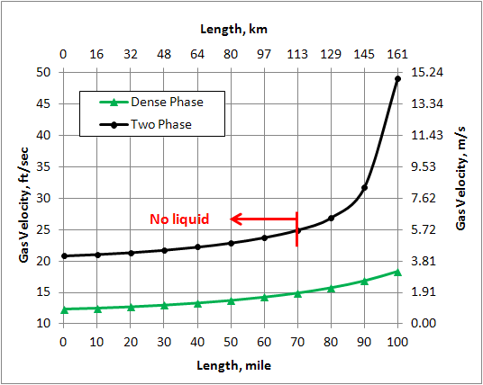
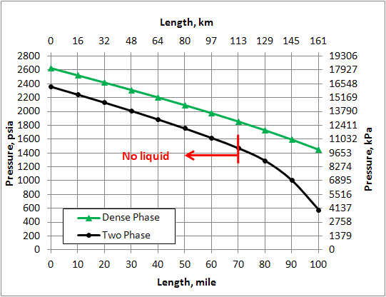
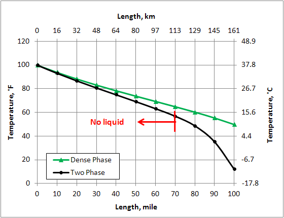
Figure 5 shows percent change of different variables of the Dense Phase with respect to the corresponding values in the Two Phase along the pipeline. The % change is defined as: . For the Two Phase case, liquid is formed to the right of the vertical red line at pipeline mile post 70 (113 km). Note that for the Dense Phase the density and viscosity increase compared to the corresponding values in the Two Phase along the pipeline. Toward the end of the line where liquid is formed in the Two Phase case, the increase in density is much higher than that of viscosity. As can be seen in Figure 5, for the Dense Phase, the pressure drop and velocity decrease in comparison to the Two Phase case. These are the factors that make Dense Phase transportation desirable.
Figure 2. Effect of inside diameter on linear pressure drop
Table 2. Summary of computer simulation results for six inside diameters.
Figure 3. Effect of inside diameter on compressor power and cooling duty requirements
Figure 4. Phase envelope, compression and cooling stages and pipeline pressure-temperature profile (ID=14 in = 356 mm)
Figure 5. Percent change of different variable in the Dense Phase compared to the corresponding values in the Two Phase along the pipeline (ID=14 in = 356 mm)
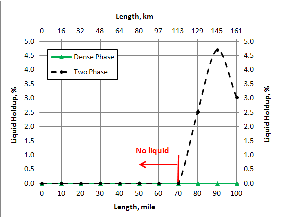
Figure 6 shows where liquid condensation in the pipeline is formed. Figure 6 also indicates that for the Two Phase case, the fluid passes through the retrograde region forming the maximum amount of liquid while no liquid is formed for the case of Dense Phase transportation.
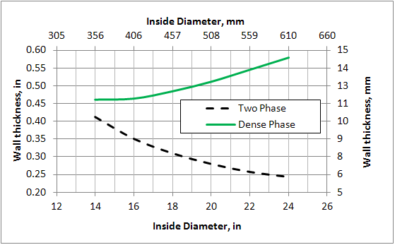
Pipeline wall thickness is an important economic factor. The wall thickness, t, for 6 diameters studies was calculated by:
Where, P is maximum allowable working pressure (assumed to be 1.1 times the inlet pressure), OD is outside diameter, E is joint efficiency (assumed to be 1), f1 is wall thickness tolerance, 0.875 to 1.0 (assumed to be 1), f2 is design factor, 0.4 to 0.72 (assumed to be 0.72 for remote area), σ is the pipe material yield stress (assumed pipe material grade X65 to be 65,000 psi or 448.2 MPa), and CA is the corrosion allowance (assumed to be 0 in or 0 mm, for dry gas). Figure 7 presents the calculated wall thickness for the 6 diameters. Notice for the Dense Phase as the diameter decreases, the wall thickness also decreases even though the pressure increases. This is a favorable impact. Opposite behavior is observed for the Two Phase case in which wall thickness increases as diameter decreases (and pressure increases).
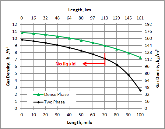
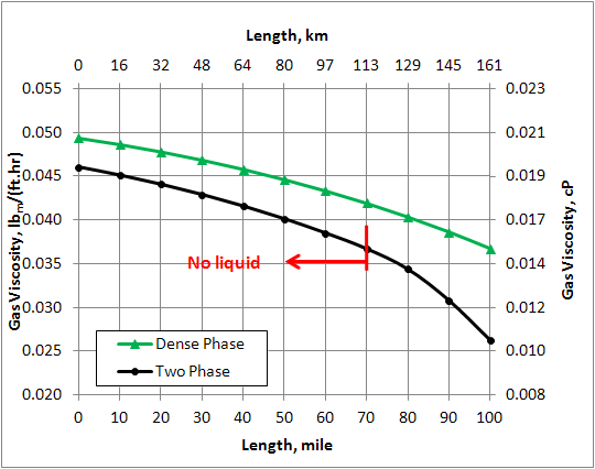
Variation of density, viscosity, velocity, pressure, and temperature along the pipe line are shown in Figures 8 through 12.
Figure 6. Variation of liquid holdup in the pipeline (ID=14 in = 356 mm)
Conclusions:
We have studied transportation of natural gas in the dense phase region and compared the results with the case of transporting the same gas using a two phase (gas-liquid) option. Our study highlights the following features:
- If the gas at the source is not at high enough pressure, considerable compression power and cooling duty may be required if the decision is to use the dense phase.
- For the dense phase, higher wall thickness is required.
- For the dense phase, smaller inside diameter is required.
- For the dense phase, the friction pressure drop is smaller.
- For the dense phase and the same diameter, the velocity is lower compared to two phase.
- For the dense phase, there is a higher potential of NGL extraction due to JT valve expansion.
- Since there is no liquid condensation in dense phase, less or no pigging is required.
Other logical results can be stated as well including:
- Composition of the gas plays an important role.
- Pipeline elevation profile and distance are important factors.
- A detailed economic analysis in terms of CAPEX and OPEX should be made for a sound comparison.
To learn more about similar cases and how to minimize operational problems, we suggest attending our G40 (Process/Facility Fundamentals), G4 (Gas Conditioning and Processing), G5 (Gas Conditioning and Processing-Special), PF81 (CO2 Surface Facilities), and PF4 (Oil Production and Processing Facilities) courses.
John M. Campbell Consulting (JMCC) offers consulting expertise on this subject and many others. For more information about the services JMCC provides, visit our website at www.jmcampbellconsulting.
By: Dr. Mahmood Moshfeghian
References:
- http://www.jmcampbell.com/tip-of-the-month/2010/01/variation-of-properties-in-the- dense-phase-region-part-2-%E2%80%93-natural-gas/
- http://www.jmcampbell.com/tip-of-the-month/2010/01/variation-of-properties-in-the- dense-phase-region-part-2-%E2%80%93-natural-gas/
- Beaubouef, B., “Nord stream completes the world’s longest subsea pipeline,” Offshore, P30, December 2011.
- ProMax 3.2, Bryan Research and Engineering, Inc., Bryan, Texas, 2011.
Figure 7. Variation of wall thickness with diameter
Figure 8. Variation of gas density in the pipeline (ID=14 in = 356 mm)
Figure 9. Variation of gas viscosity in the pipeline (ID=14 in = 356 mm)
Figure 10. Variation of gas velocity in the pipeline (ID=14 in = 356 mm)
Figure 11. Variation of pressure in the pipeline (ID=14 in = 356 mm)
Figure 12. Variation of temperature in the pipeline (ID=14 in = 356 mm)


thank you very informational
Stefan:
You are welcome. I am glad you find it informational.
Look for the follow up (Sep 2012)in which we discuss a long (1000 mile = 1610 km) pipeline transporting about 2 BSCFD.
If the same gas composition is used in Hysys dynamic to simulate the loading process up to a storage pressure above cricondenbar why hysys 7.3.1. with SRK-Twu and tuning factor predict the phase density lower than other method (and also predict a lower temperature at the and of loading).
Rachel:
I suggest the followings:
1. Plot the phase envelope to find out how it compares with phase envelope presented in this TOTM.
2. In working with HYSYS, it is better to use Peng-Robinson.
3. Please note C+7 was treated as nC8 and the original SRK was used!
I hope this helps.
Dear Mr. Mahmood Moshfeghian,
Many thanks for the wonderful insight into the dense gas properties and the dense gas hydraulics through the pipeline. It appeared all simple after reaching your article. Your article is so very well written in simple terms and well explained using graphs. Thank you very much sir, it was enlightening.
Thanks for the source.. I am eagerly looking to find the exact hysys package for supercritical fluid. I am using peng-Robinson package for high pressure compressor even though the fluid get condensed after aircooled condenser. If you have any solution to rectify the problem. kindly let me know.