In recent TOTMs (January through April, August, and September 2012 and again in January 2013), we discussed several aspects of the physical behavior and transportation of carbon dioxide (CO2) and natural gas in the dense phase. We illustrated how thermophysical properties change in the dense phase and their impacts on pressure drop calculations. The pressure drop calculation utilizing the liquid phase and vapor phase equations was compared.
In the August 2012 (TOTM), we studied transportation of rich natural gas in the dense phase region and compared the results with the case of transporting the same gas using a two phase (gas-liquid) option. Our study highlighted the pros and cons of dense phase transportation.
In September 2012 (TOTM), we analyzed pipeline transportation of a lean natural gas at a wide range of operating pressures from the relatively low pressure typical in many gas transmission pipelines to much higher pressures well into the dense phase region.
In January 2013 (TOTM), we estimated capital costs (CAPEX) as a tool to compare then selected the operating conditions and associated facilities for a long distance – high volume flow gas transmission pipeline.
In this month’s Tip of the Month (TOTM), we will revisit the January 2013 (TOTM) and continue to explore alternatives specifically for onshore natural gas transportation in pipelines. This month’s focus is also on the estimation of capital costs as a tool to compare then select the operating pressures and associated facilities for a long distance, high volume flow gas transmission pipeline.
Case Study:
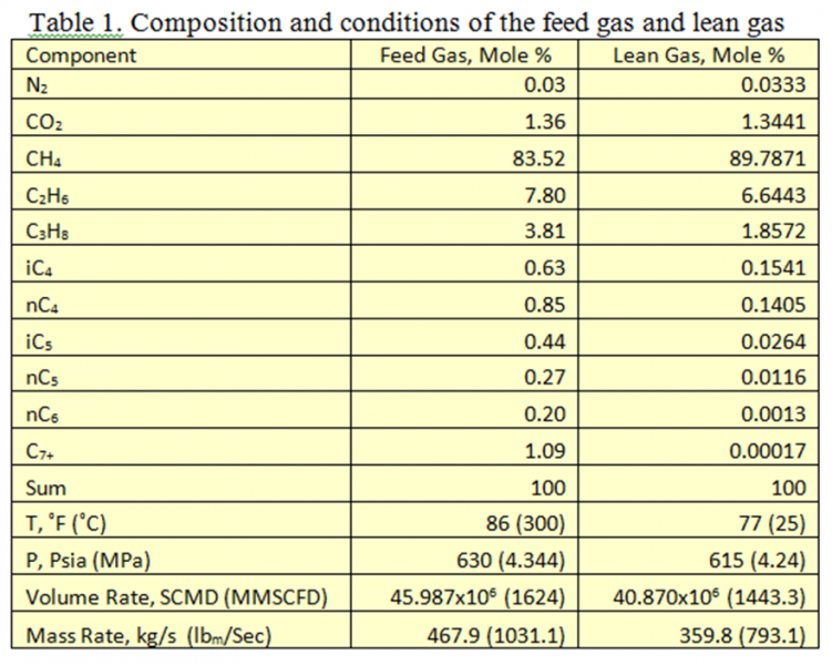
We will continue to use a similar case study basis as used in the September 2012 TOTM. The gas composition and conditions are presented in Table 1. For simplicity, the calculations and subsequent discussion will be done on the dry basis. The feed gas dew point was reduced to -40 ˚C (-40 ˚F) by passing it through a mechanical refrigeration dew point control plant. The resulting composition and conditions of the lean gas are also presented in Table 1. The lean gas has a Gross Heating Value of 40.33 MJ/Sm3 (1082 BTU/scf). The pipeline parameters are:
- Length is 1609 km (1000 miles) long
- Pipeline outside diameter is 1067 mm (42 inches) for cases A through C. Case D outside diameter is: 914 mm (36 in)
- Steady state conditions are assumed.
- Pressure at delivery point and suction at each compressor station is 7 MPa (1015 Psia)
- This is a horizontal pipeline with no elevation change.
- Overall Heat Transfer Coefficient: 1.42 W/m2-˚C (0.25 Btu/hr-ft2-˚F).
- Ambient temperature is 18.3˚C (65˚F).
- Compressor polytropic efficiency is 75%.
- Pressure drop in coolers 35 kPa (5 Psia)
- Simulation software: ProMax and using Equation of State from Soave-Redlich-Kwong (SRK).
Four cases of onshore transportation of this natural gas are considered and each is explained briefly below. The number of pipeline segments, segment length, and inlet pressure of each segment for the four cases are presented in Table 2 in the SI (System International) and field (FPS, foot, pound and second) sets of units.
Hydraulics Simulation Results and Discussions:
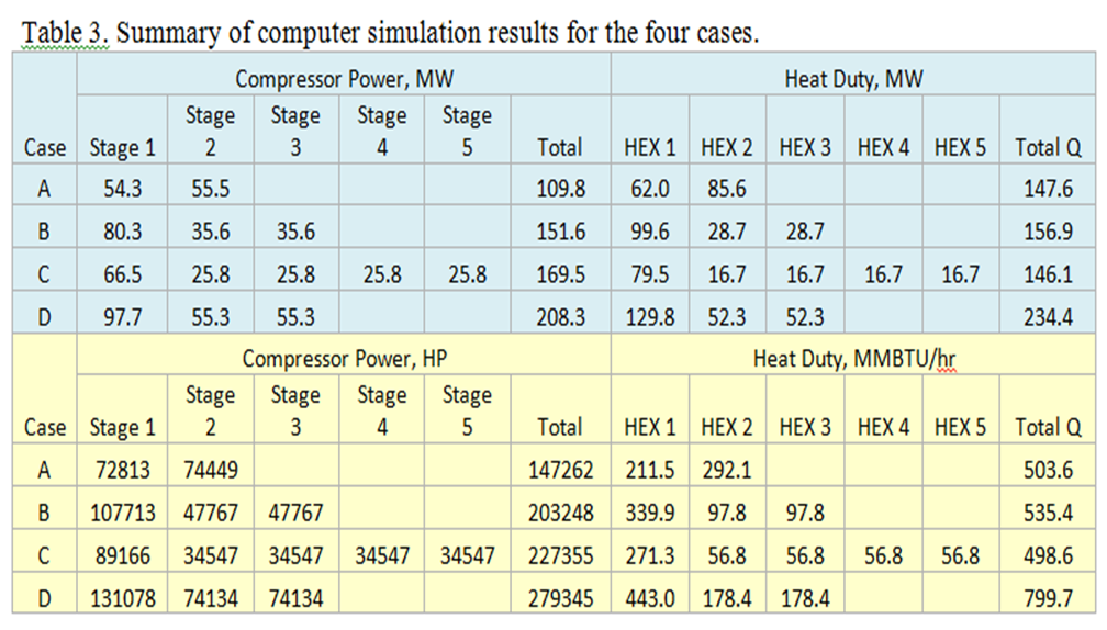
The four cases are simulated using ProMax [3] to determine the pressure and temperature profiles, the compression horsepower, and the after cooler duties. Table 3 presents a summary of simulation results for the three cases in FPS and SI systems of units.
Case A: High Pressure (Dense Phase)
This pipeline is a single compressor station configuration. The pipeline inlet pressure is in the dense phase zone. After processing and passing through the first stage scrubber, the lean gas pressure is raised from 4.24 to 9.363 MPa (615 to 1358 Psia), then cooled to 37.8 ˚C (100 ˚F). The gas is compressed further in the second stage to 20.684 MPa (3000 Psia). The high pressure compressed gas is cooled back to 37.8 ˚C (100 ˚F) and then passed through a separator before entering the long pipeline.
Case B: Intermediate Pressure
This pipeline has three compressor stations each equally spaced at 536 km (333 miles). The pipeline inlet pressure is near the dense phase zone. In the first station, the pressure is raised from 4.24 to 12.8 MPa (615 to 1858 Psia) and in the subsequent two stations, the pressure is raised from 7 to 12.8 MPa (1015 to 1858 Psia) in one stage, then cooled to 37.8 ˚C (100 ˚F), and finally passed through a separator before entering each pipeline segment.
Case C: Low Pressure
This pipeline has five compressor stations equally spaced in 322 km (200-mile) segments. In the first station, the pressure is raised from 4.24 to 10.9 MPa (615 to 1577 Psia) and in the subsequent four stations, the pressure is raised from 7 to 10.9 MPa (1015 to 1577 Psia) in one stage, then cooled to 37.8 ˚C (100 ˚F), and finally passed through a separator before entering each pipeline segment. The pipeline inlet pressure is well below that for dense phase.
Case D: High Pressure
This case is similar to case B except it operates in the dense phase and the outside diameter is 914 mm (36 inches). This pipeline has three compressor stations each equally spaced at 536 km (333 miles). The pipeline inlet pressure is in the dense phase zone. After processing and passing through the first stage scrubber, the lean gas pressure is raised from 4.24 to 8.67 MPa (615 to 1257 Psia), then cooled to 37.8 ˚C (100 ˚F). The gas is compressed further in the second stage to 17.72 MPa (2570 Psia). The high pressure compressed gas is cooled back to 37.8 ˚C (100 ˚F) and then passed through a separator before entering the long pipeline. In each subsequent station, the pressure is raised from 7 to 17.7 MPa (1015 to 2565 Psia) in one stage, then cooled to 37.8 ˚C (100 ˚F), and finally passed through a separator before entering each pipeline segment.
As can be seen in Table 3, Case A with a single compressor station requires the least total compression power and lowest heat duty requirements. The power increase for Case B (with three compressor stations) is about 38% compared to Case A and 54% and 89% for Cases C (with 5 compressor stations) and D (with 3 compressor stations), respectively. These increases in power and heat duty requirements are significant. Similarly, the heat duty increases are about 6, -1, and 59% for case B through D compared to case A, respectively.
Variation of gas pressures is shown on Figure 1 for Cases A and B. As discussed in the previous TOTM, when the phase diagram and the pressure profiles are cross plotted using the pressure and temperature profiles the pipeline outlet condition remains to the right of the dew point curve with the gas remaining as single phase.
Mechanical Design (Wall Thickness and Grade)
Pipeline wall thickness is an important economic factor. Pipeline materials have historically represented approximately 40% of the Capital Expense (CAPEX) of a pipeline. Construction has historically accounted for approximately 40% of the CAPEX as well. The estimation of the CAPEX is developed later in this TOTM. Once the wall thickness is determined, then the total weight (tonnage) of the pipeline can be calculated as well as costs for the pipeline steel.
The wall thickness, t, for the three cases is calculated from a variation of the Barlow Equation found in the ASME B31.8 Standard for Gas Transmission Pipelines:

Where,
- P is maximum allowable operating pressure, here set to 1.1 times the inlet pressure,
- OD is outside diameter,
- E is joint efficiency (assumed to be 1) since the pipeline will be joined with through thickness butt welds and 100% inspected,
- F is design factor,(ranges from 0.4 to 0.72) and here set to be 0.72 (for remote area),
- T is the temperature derating factor and is also 1.0 with the inlet temperatures no more than 37.8 ˚C (100 ˚F).
- σ is the pipe material yield stress (Grade X70 = 70,000 psi or 448.2 MPa), and
- CA is the corrosion allowance (assumed to be 0 in or 0 mm, for this dry gas).
After calculating the wall thickness, the diameter to wall thickness ratio (D/t) is checked against these rules of thumb:
- Onshore pipelines will have a maximum D/t of 72.
If the D/t calculated is too high, the wall thickness will be increased to yield the maximum allowed D/t.
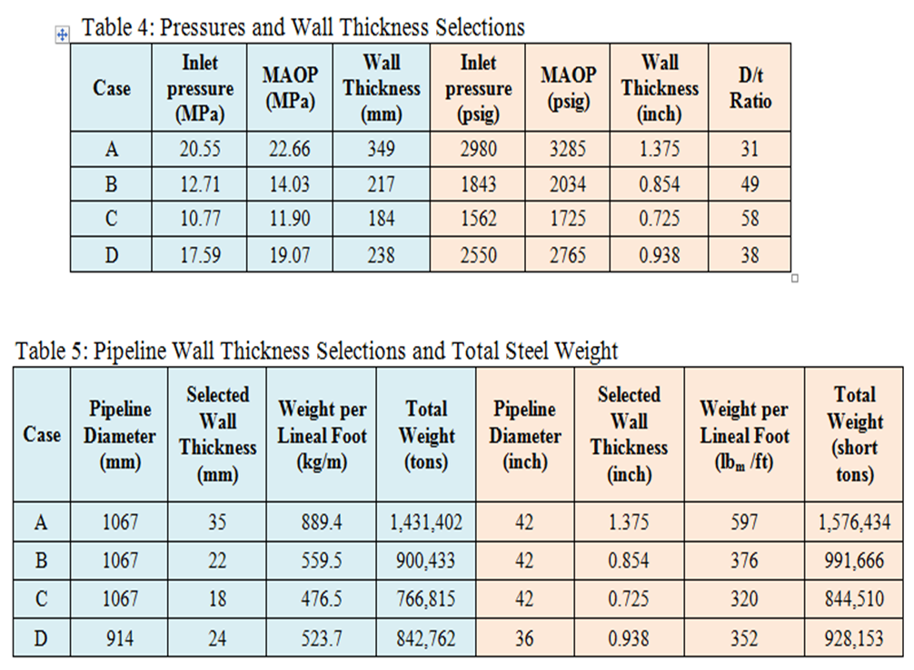
Using the calculated pipeline inlet pressures from the hydraulics as the starting point, the MAOP, and then the wall thickness can be calculated. The calculated wall thickness is then checked against the maximum D/t criteria. Table 4 summarizes these calculations for the four cases of onshore locations.
Knowing the wall thickness and diameter allows the weight per lineal length (foot or meter) to be calculated. The total weight of the steel for the 1609 km (1000 mile) long can then be calculated as well. The unit weight is given in kg/m (lbm/ft) and the total weight in metric tonnes (1000 kg) and short tons (2000 pounds). The results of these weight calculations are in Table 5.
Some observations from these calculations are:
- Decreasing the pipeline diameter from 42 inch to 36 inch does NOT dramatically reduce the total steel tonnage. This is due to the increased pressures needed to flow the same volume of gas in the smaller diameter, hence increasing the wall thickness.
- Increasing the steel grade (SMYS – Specified Minimum Yield Stress) from X-70 to X-80 would decrease the steel tonnage approximately 14%. As the cost calculations will show, this reduction would lower the cost significantly.
- The volume of steel combined with the diameter and wall thicknesses will require a major portion of pipe manufacturing capacity. If this were a sanctioned project, pipe steel procurement would need to bid well in advance of the planned construction.
- Wall thicknesses are NOT raised to next standard API thicknesses. The large quantity of steel needed allows the buyer to dictate a non-standard thickness. The pipe mills will be glad to accommodate such a requirement.
Estimated Capital Costs
The capital costs (CAPEX) for these estimates are based on two key variables: pipeline wall thickness and the compression power required. Both are dependent of the pipeline pressure profile which is dictated by the number of compressor stations. The estimated cost will be calculated from the following assumptions:
- Line pipe is priced at US$ 1200 per short ton with a 15% adder for coatings.
- Pipeline total installed cost is 2.5 times the pipe steel plus coatings cost. This factor has been surprisingly consistent historically for both onshore and offshore long distance and larger diameter pipelines. Project specific factors such as mountainous terrain for onshore pipelines can impact this cost multiplier.
- No additional cost difference is taken into account for this estimate many of the real conditions that are dealt with for the onshore design construction. In reality there is a difference that can be significant. These differences are largely dependent on the project location with factors that could include weather and seasonal challenges, terrain for onshore projects, available infrastructure and its impact on logistics, and availability of construction equipment and labor.
- Compressors and associated equipment (drivers, coolers, and ancillaries) are priced at US$ 1500 per demand horsepower.
- Onshore compressor stations are priced at US$ 25 million each for site works, buildings and equipment not directly related to gas compression.
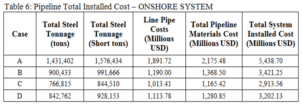
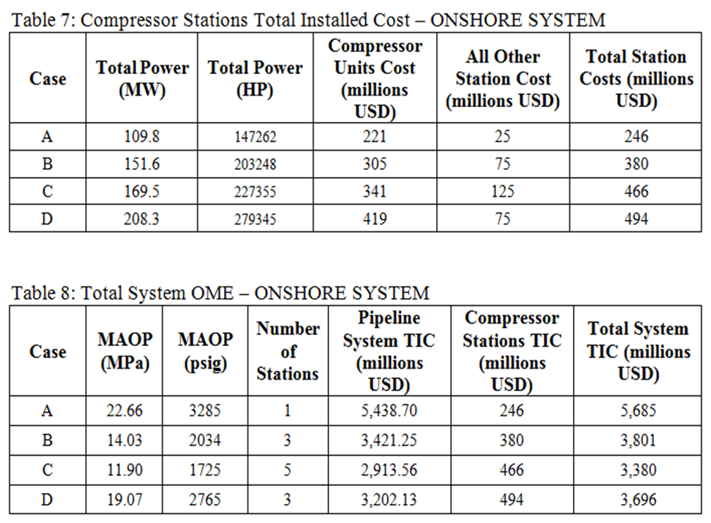
With these cost assumptions, an order of magnitude estimate (OME) for the total installed cost (TIC) is developed for the pipeline, then the compressor stations, and finally combined for the total ONSHORE pipeline system in Table 6 – Pipeline Estimate, Table 7 – Compressor Station Estimate, and Table 8 – Total System OME.
The results are indicative of finding a set of operating pressures, pipe diameter and number of compressor stations that show relatively little change with different combinations of the key parameters (Cases B, C and D). The selection of the “optimum” system configuration will involve more engineering definition, consideration of construction challenges, and evaluation of other parameters such as the operating costs (OPEX), environmental and permitting challenges, and more depth in evaluating the construction plan and costs.
The total installed costs for this ONSHORE system declines with decreasing operating pressure (MAOP), although the rate of decline is also decreasing, as more compressor stations are needed. For the onshore systems, the operating cost, particularly fuel costs, may be one of the key deciding parameters for the operating pressure / number of compressor stations decision. It is common for total life cycle costs (OPEX plus CAPEX) to begin rising at some point as the number of compressor stations and total horsepower increases with decreasing operating pressure.
Often, with the operating costs included the “optimum” configuration favors higher operating pressures and fewer compressor stations. The cost adjustments for project location on both CAPEX and OPEX can move to “optimum” configuration either way.
Final Comments:
We have studied transportation of natural gas in the dense phase region (high pressure) and compared the results with the cases of transporting the same gas using intermediate and low pressures. Our study highlights the following features:
- There may be several system configurations (pipe diameter, operating pressures, and number of compressor stations) that show relatively small variation.
- As the MAOP increases, the required power and associated cooling duty can significantly decrease.
- The decreased costs for compression are offset by increasing pipeline costs. The key is by how much.
- Project location can have significant impact on the costs, hence the key decisions are on operating pressures, and the number and power levels at the compressor stations.
- With the high power demands of large diameter – high capacity pipelines, the operating costs for fuel can be a key factor in the configuration selection. If the gas at the source is not at high enough pressure, considerable compression power and cooling duty may be required if the decision is to use the dense phase.
In future Tips of the Month, we will consider offshore transportation of natural gas as well as the effect of project location and operating costs on the life cycle costs and the configuration selection.
To learn more, we suggest attending our G40 (Process/Facility Fundamentals), G4 (Gas Conditioning and Processing), G5 (Gas Conditioning and Processing-Special), PF81 (CO2 Surface Facilities), PF4 (Oil Production and Processing Facilities), and PL4 (Fundamentals of Onshore and Offshore Pipeline Systems) courses.
John M. Campbell Consulting (JMCC) offers consulting expertise on this subject and many others. For more information about the services JMCC provides, visit our website at www.jmcampbellconsulting.com, or email us at consulting@jmcampbell.com.
By: Mahmood Moshfeghian and David Hairston
References:
- Beaubouef, B., “Nord stream completes the world’s longest subsea pipeline,” Offshore, P30, December 2011.
- http://www.jmcampbell.com/tip-of-the-month/
- ProMax 3.2, Bryan Research and Engineering, Inc., Bryan, Texas, 2012.



My brother recommended I may like this web site. He was once totally right. This post truly made my day. You cann’t imagine just how much time I had spent for this info! Thank you!
Very good and excellence case study. Can you please send to me the pdf file